Showing posts with label Occlusion. Show all posts

Thursday, August 27, 2015

Voxel Occlusion

Real time rendering systems (like the ones in game engines) have two big problems to solve: First to determine what is visible from the camera's point of view, then to render what is visible.

While rendering is now a soft problem, finding out what is potentially visible remains difficult. There is a long history of hackery in this topic: BSP trees, PVS, portals etc. (The acronyms in this case make it sound simpler.) These approaches perform well for some cases to then fail miserably in other cases. What works for indoors breaks in large open spaces. To make it worse, these visibility structures take long to build. For an application where the content constantly changes, they are a very poor choice or not practical at all.

Occlusion testing on the other hand is a dynamic approach to visibility. The idea is simple: using a simplified model of the scene we can predict when some portions of the scene become eclipsed by another parts of the scene.

The challenge is how to do it very quickly. If the test is not fast enough, it could still be faster to render everything than to test and then render the visible parts. It is necessary to find out simplified models of the scene geometry. Naturally these simple, approximated models must cover as much of the original content as possible.

Voxels and clipmap scenes make it very easy to perform occlusion tests. I wrote about this before: Covering the Sun with a finger.

We just finished a new improved version of this system, and we were ecstatic to see how good the occluder coverage turned out to be. In this post I will show how it can be done.

Before anything else, here is a video of the new occluder system in action:


A Voxel Farm scene is broken down into chunks. For each chunk the system computes several quads (a four vertex polygon) that are fully inscribed in the solid section of a chunk. They also are as large as possible. A very simple example is shown here, where a horizontal platform produces a series of horizontal quads:


These quads do not need to be axis aligned. As long as they remain inside the solid parts of the cell, they could go in any direction. The following image shows occluder quads going at different angles:


Here is how it works:

Each chunk is generated or loaded as a voxel buffer. You can imagine this as a 3D matrix, where each element is a voxel.

The voxel buffer is scanned along each main axis. The following images depict the process of scanning along one direction. Below there is a representation of the 3D buffer as a slice. If this was a top down view, you can imagine this is a vertical wall going at an angle:
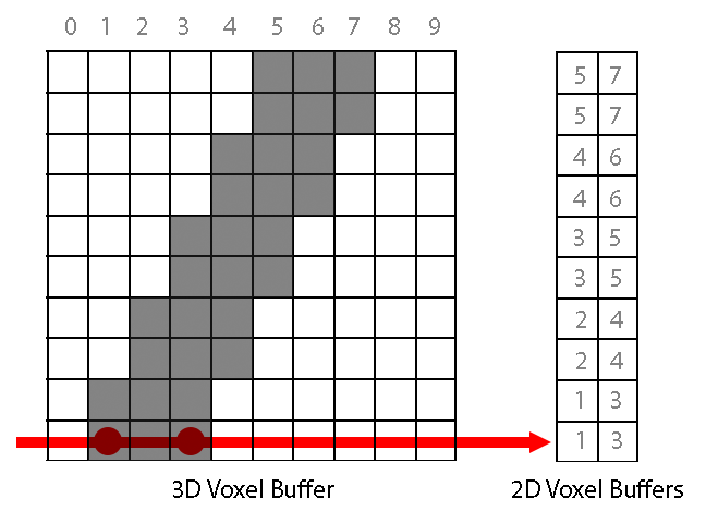
For each direction, two 2D voxel buffers are computed. One stores where the ray enters the solid and the second where the ray exits the solid.

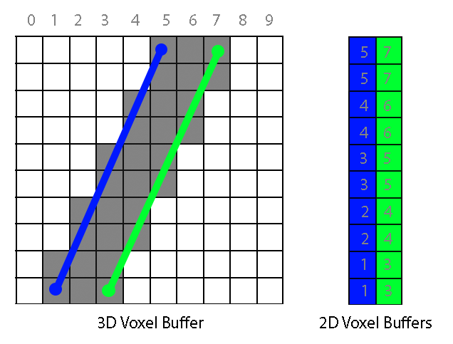
For each 2D buffer, the maximum solid rectangle is computed. A candidate rectangle can grow if the neighboring point in the buffer is also solid and its depth value does not differ more than a given threshold.

Each buffer can produce one quad, showing in blue and green in the following image:
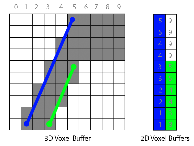
Here is another example where a jump in depth (5 to 9) makes the green occluder much smaller:
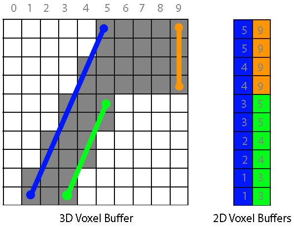
In fact, if we run again the function that finds the maximum rectangle on the second 2D buffer it will return another quad, this time covering the missing piece :
Once we have the occluders for all chunks in a scene, we can test very quickly whether a given chunk in the scene is hidden behind other chunks. Our engine does this using a software rasterizer, which renders the occluder quads to a depth buffer. This buffer can be used to test all chunks in the scene. If a chunk's area on screen is covered in the depth  buffer by a closer depth, it means the chunk is not visible.

This depth buffer can be very low resolution. We currently use a 64x64 buffer to make sure the software rasterization is fast. Here you can see how the buffer looks like:


It is also possible not to use our rasterizer test at all and feed the quads to a system like Umbra. What really matters is not how the test is performed, but how good and simple the occluder quads are.

While this can still be improved, I'm very happy with this system. It is probably the best optimization we have ever done.


Tuesday, May 7, 2013

Covering the Sun with a finger

The oldest optimization in real-time graphics is to avoid rendering what you don't see. When you explain this to people who are not in the field, they usually shrug and say something in the line of "Duh, Sherlock".

It is easier said that done. Well, actually a big part of it is quite easy. The first trick you see in all graphics books is to render only what's inside the field of view. While the scene surrounds entirely the camera, the camera only captures a narrower slice of it. Anything outside this slice, which is usually 90 degrees along the horizontal, does not need to render. For a mostly horizontal scene, only 90 degrees out of 360 need to be rendered. This simple optimization reduces scene complexity four times. Another way to put it is, now you can have four times more detail without a performance drop. This technique is called Frustum Culling.

Frustum Culling is a no-brainer for small objects that are scattered around the scene. As scene complexity rises you must batch as many objects together as possible. The need for aggressive batching apparently has relaxed a bit recently, but there is no question that batching is still necessary. This goes against Frustum culling. What if there is an entire batch that is only partially in the field of view? You would still need to render it all. So, the more you batch, the more you can loose from the frustum culling optimization... unless your batches are somehow compatible with the scene slices you need to render. More to that later.

Even if you were able to perfectly cull all the information outside the field of view, there is usually a lot of polygons being rendered in a scene that never make it to the screen as pixels. This is because they become hidden later by a closer polygon.

Imagine a huge mountain with a valley behind it. If the mountain was not there you would see the valley. With the mountain in front of you, all the efforts rendering this valley go to waste. If we could somehow detect we can skip this valley, we would save a lot of rendering. We could have a much nicer mountain.

This technique is called Occlusion Culling. It is in principle a difficult problem, as the final rendering is the ultimate test of what is really visible and what not. Obviously some sort of approximation or model has to be used. A simpler model of the scene allows to estimate what portions of the final rendering will become hidden so it is safe to skip them.

And then again, if you had the occlusion problem perfectly solved, you would still have the issue with batching. It is not that different than with frustum culling. Maybe just a small clip of a large batch is visible, still that would require the entire batch to render... unless your batches are somehow compatible with the scene volumes being occluded.

I wondered that maybe there was a single approach that would help with all these issues at once. Yes, some sort of silver bullet. I set out to look for one, and did find something. Well maybe it is not a silver bullet, but it is quite shinny.

It is about the geometry clipmaps. I have covered them many times in the past. The idea is somewhat simple: if your world can be represented as an octree, you can compute any scene from this world as as series of concentric square rings. Each ring is made of cubic cells. The size of these cells grow exponentially as the rings are farther from the viewer.


The image above shows a projection of a clipmap in 2D.

You can see right away how this helps with batching and frustum culling. Each cell is an individual batch, which can contain a few thousand polygons. It is quite simple to determine whether a cell is inside the field of view. Also, cells go out of the field of view quite efficiently as their size is constrained by their very definition.

The clipmap turned to be very friendly for occlusion testing as well. Imagine you could identify some cells as occluders in one specific direction of the clipmap. It becomes fairly simple to test if more distant cells are occluded or not.

The following image shows how this principle works:


Here four cells have been identified as occluders. They show as vertical red lines. Thanks to them, we can safely assume all the cells painted in dark red can be discarded. These batches are never sent to the graphics card.

In my case I am performing the tests doing software rasterization. It is very fast because the actual cell geometry is not rendered, only cell aligned planes. So far a depth buffer of 64x64 provides sufficient resolution.

Not bad!

Sunday, April 28, 2013

Video Update for April 2013

An update about clouds and a surprise topic for the second part.


Making these recordings feels a bit weird. I love talking to real audiences, but this feels more like leaving a message in someone's answering machine.